NEWS, EVENTS & BLOG
BLOG

The Clash Between IPC Class 3 Requirements and Shrinking Geometries
![]() Press Office, VersaLogic Corporation, 09/01/21
Press Office, VersaLogic Corporation, 09/01/21
Sometimes the rate of change of technology overtakes the standards intended to ensure the quality of that technology. A case in point is the IPC Class 3 requirement for printed circuit boards (PCB). The international standards organization, IPC, defines three classes for bare PCBs, based on the level of reliability required. These are summarized in the following table:
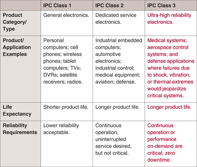 IPC Class 1, 2, and 3 overview
Let’s look at a specific issue that highlights the clash between the existing Class3 PCB requirements, and the conflict with BGA (ball grid array) chip technology.
Annular Rings vs. Advances in Ball Grid Array Technology
The challenge for Class 3 came as the authors of the Class 3 specifications in the 1960’s had no visibility of the high-density ball grid array (BGA) packages available today. A BGA is a type of surface-mount packaging used for integrated circuits. BGAs offer a high number of interconnection pins in a smaller area by utilizing the bottom surface of the device, instead of just the perimeter.
The IPC specifications were written to regulate PCB quality. One aspect is the definition of standards of accuracy regarding where the holes need to be drilled through the PCB in relation to via pads. Via pads are required when signals from a BGA package must be routed down to other layers in the stack-up. The most challenging situation is the case where traces must be run between BGA pads which also incorporate vias. Class 3 requires that the minimum width of the annular ring surrounding the via hole is 2 mils (0.05 mm). The diagram below shows the acceptable conditions for Classes 1, 2 and 3.
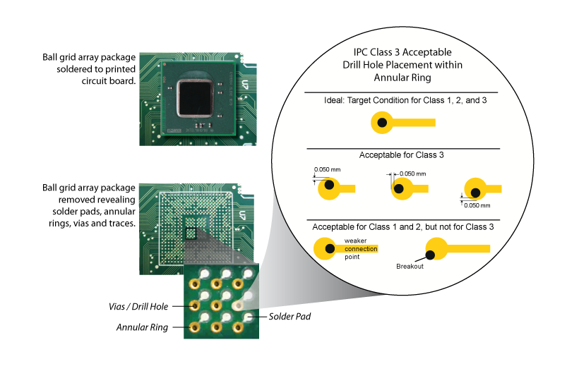 Class 3 acceptable drill-hole placement within annular rings and via pads
Given the practicalities concerning manufacturing tolerances and drill wander, this leads to an annular ring diameter of 24 mils being required to accommodate an 8 mils diameter drill hole. In addition to that, a 2 mils clearance is required around the annular ring to provide spacing from other conducting features such as traces.
When considering routing traces between BGA via pads, there is a minimum BGA pitch at which an acceptably thin trace (4 mil) can be routed.
As package sizes decreased and the ball count remained the same, or even increased, the pitch between balls has reduced significantly. Whereas Class 3 could accommodate a BGA pitch of 1 mm, it cannot handle BGA pitches ≤0.8 mm. Today there are system on chip (SOC) devices, such as the Intel Atom E3900 family (Apollo Lake), that have BGA pitches of ~0.6 mm.
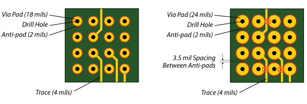 Class2 (left) works for BGA pitches ≤0.8 mm, whereas Class3 (right) does not
As can be seen above, the minimum trace width of 4 mils is unrouteable in a Class 3 design when pitches of ≤0.8 mm are involved.
Solution to the “Density” vs. Ultra-High Reliability Conundrum
In the absence of an industry standard for using fine-pitch BGA components in ultra-high reliability board designs, SBC suppliers, such as VersaLogic, have developed innovative design and manufacturing techniques to achieve the integrity and intent of Class 3 in their leading-edge products.
After experimenting with several approaches, VersaLogic developed a solution that reliably solved the challenge. It was a two piece solution that provides ultra reliable products while supporting modern small geometry BGA chips. First is the use of a larger 8 mil mechanical drill for via holes to control drill wander and plating issues. Second is to change the standard circular annular rings to a slightly larger teardrop-shaped via pad as shown below.
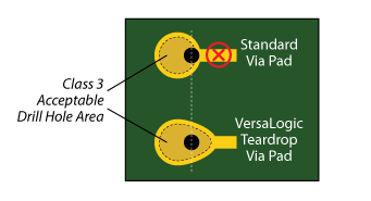 Teardrop-shaped via pads provide maximum drill margins to offset drill wander and registration issues
The teardrop pad provides the necessary drill margin in the area of the neck where the trace meets the pad. In this design, even if the drill wanders closer to the neck of the pad, there is still a sufficient margin of copper between the hole and the edge of the pad to maintain a reliable connection. The use of the teardrop pad, along with tight manufacturing tolerances and controls used by VersaLogic, provide a reliable electrical and mechanical connection at each via. This combination of design and manufacturing expertise enables the production of a high reliability product, using the latest BGA packages.
For more information on the challenges and VersaLogic’s solution please see the whitepaper: Ultra Reliable Embedded Computing: The Clash between IPC Class 3 Requirements and Shrinking Geometries.
Class 3 Boards
VersaLogic has a number of products that can be built and inspected to Class 3 standards. These are:
- Lion, PC/104 Format Single Board Computer, VL-EPMe-42
- Liger, PC/104 Embedded Computer, VL-EPM-43
- Anaconda, EBX Single Board Computer, VL-EBX-18
- Analog Input, 8 Channel, 12-Bit, Mini PCIe Card, VL-MPEe-A1
- Analog Input, 8 Channel, 16-Bit, Mini PCIe Card, VL-MPEe-A2
- Dual CAN Bus Interface, Mini PCIe Card, VL-MPEu-C1E
- Fiber-Optic Ethernet, Mini PCIe Card, VL-MPEe-E4E
- Dual Ethernet, Mini-PCIe Card, VL-MPEe-E5EC
- Dual Ethernet, Mini-PCIe Card with Acrylic Conformal Coating, VL-MPEe-E5ECA
- Dual Ethernet, Mini-PCIe Card with Urethane Conformal Coating, VL-MPEe-E5ECU
- GPS Receiver, Mini PCIe Card, VL-MPEu-G2
- Advanced GPS Receiver, Mini PCIe Card, VL-MPEe-G3
- SATA Interface, Mini PCIe card, VL-MPEs-S3
- Serial I/O, Mini PCIe Card, VL-MPEe-U2E
- Video Expansion Module, Mini PCIe Card, VL-MPEe-V5EC
More Information
Want to know more about VersaLogic’s range of embedded products? Let’s start a conversation.